
4000 Series Local Pressure Controller

Submitted by divya on July 15, 2025
4000 Series Local Pressure Controller

4000 Series Local Pressure Controller

  • Repeatability: 0.5% of sensing element range
  • Deadband: 0.1% of output span
  • Differential Gap: 15-100% of sensing element range
  • Output Signal Range: 3-15 PSIG (0.21-1.03 BARG) or 6-30 PSIG (0.41-2.07 BARG)
  • Standard Temperature Limitations: -40°F to 160°F (-40°C to 71°C) 

More Details

4000 Series pressure controllers have two modes of operation: Proportional Only & Proportional + Reset. Control action is field reversible between direct acting and reverse acting. These controllers meet or exceed EPA emission standards, with standard controllers NACE ready with stainless steel parts.

Overview


4000 Series Local Pressure Controller

MODEL DESCRIPTION
   
4000 Proportional Only Controller
   
4010 Proportional-Plus-Reset Controller
   
4020 Bellows Sensing Controller
   
4030 Differential Gap Controller

Print

|

Back to Top

BOURDON TUBE PRESSURES AND MATERIALS
PRESSURE RANGES MAXIMUM ALLOWABLE STATIC PRESSURE LIMIT MATERIALS
PSIG BARG PSIG BARG
0 - 30 0 - 2.07 30 2.07 S31600
0 - 60 0 - 4.14 60 4.14 S31600
0 - 100 0 - 6.89 100 6.89 S31600
0 - 200 0 - 13.79 200 13.79 S31600
0 - 300 0 - 20.68 300 20.68 S31600
0 - 600 0 - 41.37 600 41.37 S31600*
0 - 1,000 0 - 68.95 1,000 68.95 S31600*
0 - 1,500 0 - 103.42 1,500 103.42 S31600*
0 - 3,000 0 - 206.84 3,000 206.84 S31600
0 - 5,000 0 - 344.74 5,000 344.74 S31600
 NOTES: * AVAILABLE IN N05500 (OTHER MATERIALS AND RANGES ARE SPECIAL ORDER).
SUPPLY PRESSURE REQUIREMENTS
OUTPUT SIGNAL RANGE
THROTTLING (ON/OFF)
NORMAL OPERATING SUPPLY PRESSURE (1) MAXIMUM ALLOWABLE SUPPLY PRESSURE TO PREVENT INTERNAL PART DAMAGE STEADY-STATE AIR CONSUMPTION
SCFH (STANDARD CUBIC FEET PER HOUR)
PSIG BARG PSIG BARG PSIG BARG PROPORTIONAL BAND
 SET TO 5
PROPORTIONAL BAND
SET TO 0 OR 10
0-15 (0-20) 0.21-1.03 (0-1.03) 20 1.38 40 2.76 MINIMUM 10
MAXIMUM 34
MINIMUM 2
MAXIMUM 30
6-30 (0-35) 0.41-2.07 (0-2.41) 35 2.41 40 2.76 MINIMUM 10
MAXIMUM 34
MINIMUM 5
MAXIMUM 6
NOTES: (1) CONTROL MAY BE DEGRADED IF THIS PRESSURE IS EXCEEDED.

Printable view

BOURDON TUBE PRESSURES AND MATERIALS
PRESSURE RANGES MAXIMUM ALLOWABLE STATIC PRESSURE LIMIT MATERIALS
PSIG BARG PSIG BARG
0 - 30 0 - 2.07 30 2.07 S31600
0 - 60 0 - 4.14 60 4.14 S31600
0 - 100 0 - 6.89 100 6.89 S31600
0 - 200 0 - 13.79 200 13.79 S31600
0 - 300 0 - 20.68 300 20.68 S31600
0 - 600 0 - 41.37 600 41.37 S31600*
0 - 1,000 0 - 68.95 1,000 68.95 S31600*
0 - 1,500 0 - 103.42 1,500 103.42 S31600*
0 - 3,000 0 - 206.84 3,000 206.84 S31600
0 - 5,000 0 - 344.74 5,000 344.74 S31600
 NOTES: * AVAILABLE IN N05500 (OTHER MATERIALS AND RANGES ARE SPECIAL ORDER).
SUPPLY PRESSURE REQUIREMENTS
OUTPUT SIGNAL RANGE
THROTTLING (ON/OFF)
NORMAL OPERATING SUPPLY PRESSURE (1) MAXIMUM ALLOWABLE SUPPLY PRESSURE TO PREVENT INTERNAL PART DAMAGE OUTPUT SIGNAL STEADY-STATE AIR CONSUMPTION (2)
SCFH (STANDARD CUBIC FEET PER HOUR)
PSIG BARG PSIG BARG PSIG BARG PSIG BARG
3-15 (0-20) 0.21-1.03 (0-1.38) 20 1.38 40 2.76 0 0 1.6
5 0.34 1.5
10 0.69 1.4
20 1.38 0.3
6-30 (0-35) 0.41-2.07 (0-2.41) 35 2.41 40 2.76 0 0 2.6
5 0.34 2.6
10 0.69 2.6
20 1.38 2.6
30 2.07 2.5
35 2.41 0.3
NOTES: (1) CONTROL MAY BE DEGRADED IF THIS PRESSURE IS EXCEEDED.
(2) SCFH: STANDARD CUBIC FEET PER HOUR = FT3/HR. @ 60°F AND 14.7 PSIG. AIR FLOW RATE INDICATED, FOR NATURAL GAS FLOW RATE - MULTIPLY BY 1.29.

Printable view

4000 Series Pressure Controller Documentation

Refer to our FloSpec software for product selection, sizing and ordering

supplier

GripTight® Test Plug

Submitted by Shilpa on July 15, 2025

GripTight® Test Plug


Test Open End Pipe, Pipelines, Tubes and Pressure Vessels Quickly and Safely

  • I.D. Sealing Version
  • Pressures to 14,000 psi (960 Bar)
  • Sizes from .93" to 8.53" (23.6mm - 216.7mm) In Stock
  • Larger Sizes through 42" (1066.8 mm) Available


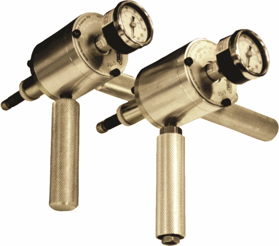
High pressure pipe testing is safer than ever before, thanks to EST Group's GripTight® Test Plugs. Unlike other pipe testing plugs that can loosen and eject under high pressure - even becoming dangerous projectiles - the GripTight Test Plugs actually use test pressure to seal more securely against the pipe's inner diameter. The greater the pressure - the greater the grip! The result is safer installation, better sealing and all around safer testing.

Test Plug Purpose & Functionality

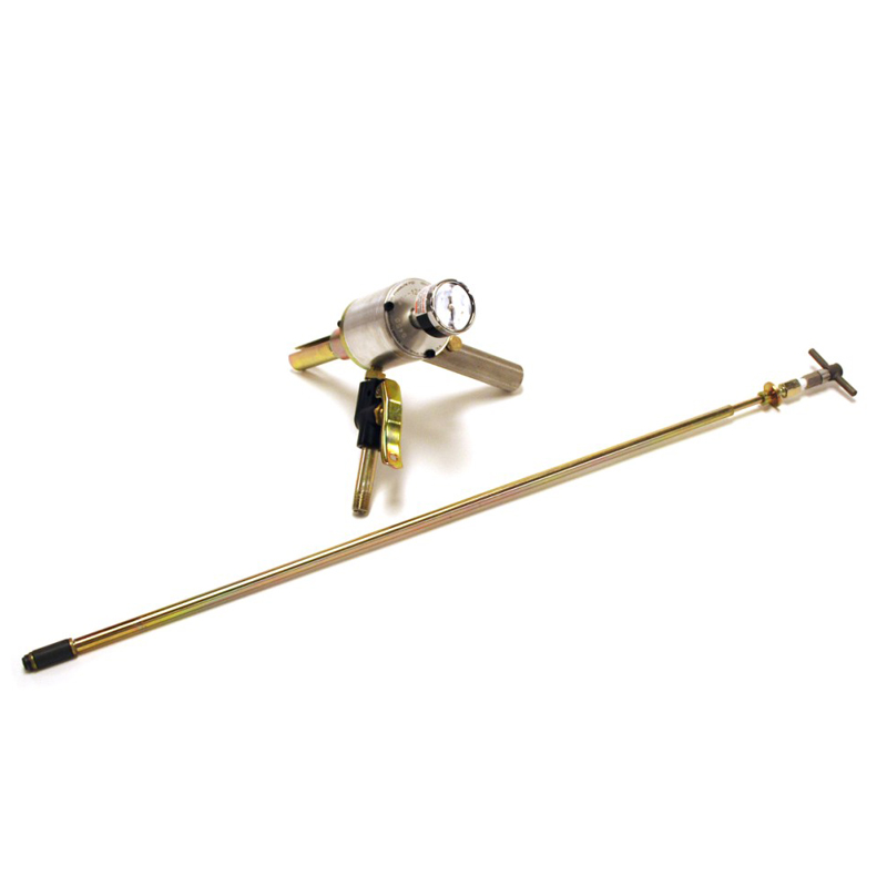
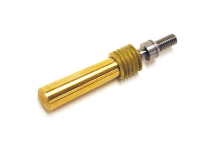
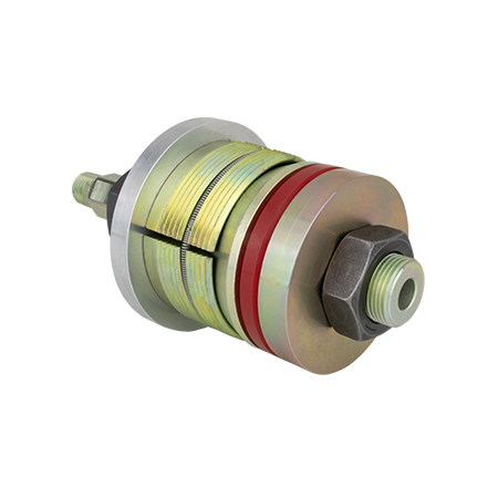
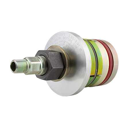
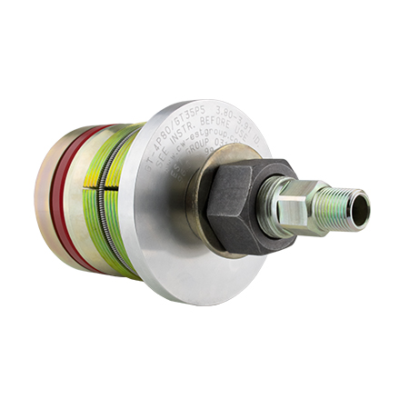
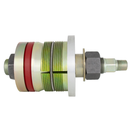
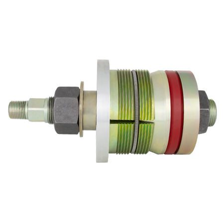
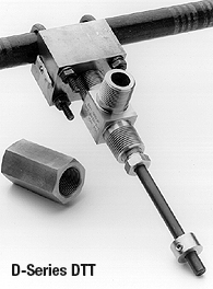
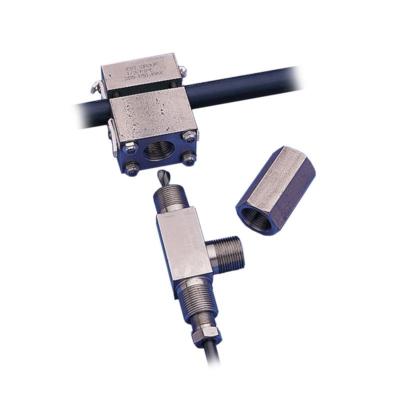
GripTight Test Plugs provide a fast, safe and reliable solution for testing open ended pipe. Capable of achieving test pressures up to 14000 PsiG (960 BarG), GripTight Test Plugs eliminate the need for welding on and cutting off end caps, saving time and money on every test. The self-gripping design uses test pressure to supplement the plug’s pressure holding capability - the greater the test pressure, the greater the grip. GripTight Test Plugs incorporate a ported shaft for easy filling, venting and draining of the test system. GripTight Test Plugs are reusable, further reducing the cost per test. Wear components (seals and gripper assemblies) are field replaceable.

Basic Operation:

  • Verify pipe size (Outer Diameter, Wall Thickness, and Inner Diameter), schedule, and material
  • Place plug into the inner diameter of the pipe
  • Tighten the Compression Nut to the required installation torque
  • Fill the pipe with the test medium
  • Pressurize the pipe, hold for the required time limit
  • Depressurize and drain test medium
  • Loosen Compression Nut and remove the GripTight Test Plug


Test Plug Features & Benefits


  • Safe: Pressure on plug squeezes grippers tighter; plug can not be ejected under pressure when properly installed
  • High Pressure Performance: Have been used for pipe burst tests in a manufacturing environment. Tests at higher pressure with greater safety, typically to 80% of yield
  • Eliminates Weld Caps: No welding or cutting required. Speeds fabrication testing, reducing test times up to 80%
  • Engineered Seal Design: Reduces seal wear for long lasting performance
  • Optional High Pressure Pipe Cap: Plugs can be used in solid or ported configurations
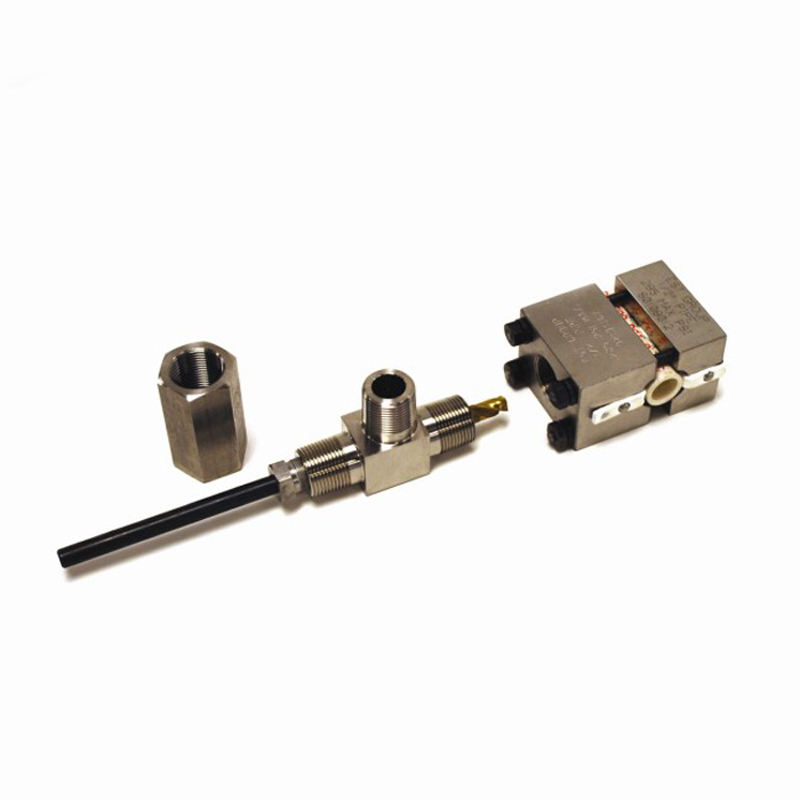
  • Positioning Washer: Prevents plug loss in pipe end, and eliminates plug lock-up after hydro test, common with inferior plug designs
  • Retaining Spring: Assures retraction of gripper segments. Superior to O-ring design
  • Easy to Maintain: Replacement seals and grippers readily available and easy to replace
  • Optional Seals: Viton®, Silicone, EPDM
  • The Self-Gripping design provides unparalleled safety - the greater the test pressure, the greater the grip.
  • The GripTight Test Plugs are reusable. Drastically reducing the cost per test by up to 80% compared to welded-on end cap


FAQS

What installation equipment is required for a GripTight Test Plug?

A standard torque wrench & appropriate size crows foot or extra-deep socket.

What is the lead time for a standard GripTight Test Plug?

A majority of sizes are available from stock and are eligible for same day shipping. If items are not in stock, every effort will be made to meet your scheduling needs.

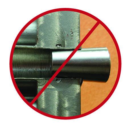
Does the pipe need to be in a specific condition before the GripTight Test Plug can be installed?

Yes. The GripTight Test Plug is designed for use in smooth bore pipe to achieve the desired functionality. If corrosion, pitting, scale, or a seam weld is present, then some preparation is required prior to testing.

What is the average amount of time required to install and perform a pressure test with the GripTight Test Plug?

Depending on the volume of the application, the pressure tests can be completed in as little as 10 minutes from insertion to removal.

Can one GripTight Test Plug be used to test multiple pipe sizes?

No. They are size specific to the schedule of the pipe.

What is the standard seal material for the GripTight Test Plug and are alternate seal materials available?

Urethane is the standard seal material for a GripTight Test Plug. Alternate seal materials are available; the most common replacement seal material options consist of Fluoroelastomer, Neoprene, Silicone, EPDM, Natural Rubber, Nitrile/Buna-N, and SBR/ Buna-S

What is the desired test medium?

While hydrostatic testing is the safest means for accomplishing a pressure test since water is a non-compressible medium, the selfgripping feature of the GripTight Test Plug does not recognize a difference in the test medium.

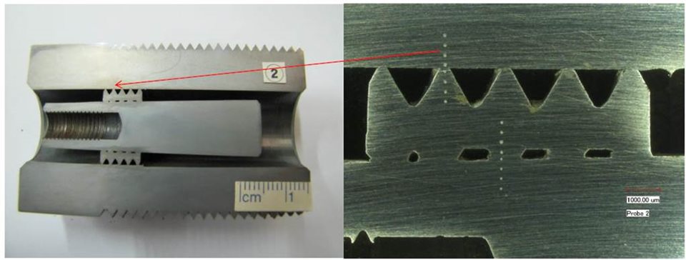
Is there visible scarring from the grippers after the test has been completed?

At high pressure, minimal marring of the pipe can occur due to the gripper engagement. Customers have reported that gripper indentations may range in depth from 0.005” to 0.015” (0.13 - 0.38 mm), significantly less than the depth of a pipe imperfection that would require a weld repair

A pressure test plug like our Griptight Test Plug is the safest component for high-pressure pipe testing on the market. It allows operators to insert thermometers and gauges into the system to check the pressure and temperature.

Pipe pressure test plugs are a fast, safe and reliable solution for testing open ended pipe. This tool enables the operator to perform a pressure test on an open pipe or vessel, whilst eliminating the need to weld on pipe caps or flanges, to carry out hydrostatic test applications.

A pressure test plug like our Griptight Test Plug is the safest component for high-pressure pipe testing on the market. It allows operators to insert thermometers and gauges into the system to check the pressure and temperature.

High pressure pipe testing is safer than ever with Curtiss Wright EST’s Griptight Test Plugs.

Further Information

The EST Division specializes in developing, manufacturing, and marketing highly-engineered products and repair services.

If you would like to contact us and speak to a sales representative, please fill out a contact form.

Product Images

CAPTCHA
This question is for testing whether or not you are a human visitor and to prevent automated spam submissions.

DFN Yokeless Spring & Diaphragm Actuator

Submitted by divya on July 15, 2025
DFN Yokeless Spring & Diaphragm Actuator

DFN Yokeless Spring & Diaphragm Actuator

  • 35 PSIG (2.41 BARG) Input Signal
  • 2-7/8" (73mm) or 3-7/8" (99mm) Bolt Circle Diameter
  • -40°F to 180°F (-40°C to 82°C) Standard Temperature Limitations

More Details

The DFN is a bracket-mounted, direct acting, spring and diaphragm actuator. DFN actuators are typically used to operate butterfly valves, chokes and louvers for throttling or on/off control.

Overview

Options
 
  • Travel Stop Options Available
  • Heavy Duty Protective Coatings Available

Print

|

Back to Top

Product Specifications

DFN Specifications
 
AVAILABLE DFN OPERATING PRESSURE, DIAPHRAGM AREA AND THRUST
ACTUATOR SIZE MAXIMUM TRAVEL
(WITH STANDARD TRAVEL STOP)
MAXIMUM CASING PRESSURE EFFECTIVE DIAPHRAGM AREA ACTUATOR SPRING CODE OPERATING RANGE NET STEM FORCE
STEM FULLY RETRACTED (1) STEM FULLY EXTENDED (2)
INCH mm PSIG BARG INCH2 cm2 PSIG BARG lbf N FORCE DIAPHRAG LOADING PRESSURE
lbf N PSIG BARG
069 3-1/2 89 65 4.48 69 445 WHITE 3.1-12.7 0.21-0.88 330 1,468 545 1,205 20 1.38
DARK GREEN 6-27.4 0.41-1.9 630 2,802 270 1,201 30 2.07
156 4-1/8 105 40 2.76 160 1,032 NONE (BLACK) 3.7-13.1 0.26-0.90 796 3,541 1,205 5,360 20 1.38
GOLD/BLUE 7.1-27 0.49-1.9 1,462 6,503 682 3,034 30 2.07
NOTES: (1) Stem force equals the initial spring compression with zero loading pressure.
(2) Stem force equals the loading pressure multiplied by the diaphragm area with the stem fully extended minus the force at maximum compression.

Printable view

DFN Actuator Documentation

Refer to our FloSpec software for product selection, sizing and ordering

supplier

DFRP Rotary Pneumatic Piston Actuator

Submitted by divya on July 14, 2025
DFRP Rotary Pneumatic Piston Actuator

DFRP Rotary Pneumatic Piston Actuator

  • 20 PSIG (1.38 BARG) Minimum Cylinder Operating Pressure
  • 1/2" (12.7mm) to 2-1/2" (63.5mm) Valve Shaft Compatibility
  • 90 Degree Rotation
  • -40°F to 180°F (-40°C to 82°C) Standard Temperature Limitations

More Details

DFRP rotary double-acting pneumatic piston actuators are designed for high torque applications. When combined with a positioner or a two-position control signal, DFRP actuators can be used for throttling or on/off control. DFRP actuators will always require a volume tank in order to hold a fail position.

Overview

Options
 
  • Handwheels and Travel Stop Options Available
  • Versatile Instrument Mounting Options
  • Splined Connection
  • Unique Design Allows For Low-Cost Cylinder Replacement
  • Heavy Duty Protective Coatings Available

Print

|

Back to Top

Product Specifications

DFRP Specifications
 
AVAILABLE VAVLE SHAFT COMPATIBILITY
VALVE SHAFT CONNECTION SIZES ACTUATOR SIZES
INCH mm 028 079 113 113 154
3/4 19.1 ü ü ü û û
7/8 22.2 ü ü ü û û
1 25.4 ü ü ü û û
1-1/4 31.8 ü ü ü û û
1-1/2 38.1 ü ü ü û û
1-3/4 44.5 ü ü ü ü ü
2 50.8 ü ü ü ü ü
2-1/8 54 ü ü ü ü ü
2-1/2 63.5 û û û ü ü
4 101.6 û û û ü ü
AVAILABLE DFRP OPERATING PRESSURE, PISTON AREA AND TORQUE
ACTUATOR SIZE MAXIMUM OPERATING PRESSURE PISTON AREA 0–90 DEGREE MAXIMUM TORQUE TORQUE PER PSIG
PSIG BARG INCH² cm² lbf-in N•m lbf-in N•m
028 110 7.58 28.27 182 7,104 9,626 87 5.31
079 100 6.89 78.54 507 13,800 18,710 175 19.77
112 85 5.86 113.1 730 16,896 22,913 199 22.48
113 110 7.58 113.1 730 56,004 75,926 373 42.14
154 110 7.58 153.94 993 65,004 88,128 433 48.92
AVAILABLE DFRP CYLINDER DISPLACEMENT FOR 90 DEGREE ROTATION
ACTUATOR SIZE ACTUATOR PISTON POSITION
PISTON UP PISTON DOWN
INCH3 cm3 INCH3 cm3
028 125 2,048 131 2,147
079 361 5,916 369 6,047
112 517 8,472 564 9,242
113 942 15,437 997 16,338
154 1,290 21,139 1,361 22,303

Printable view

DFRP Actuator Documentation

Refer to our FloSpec software for product selection, sizing and ordering

supplier

DFLP Linear Pneumatic Piston Actuator

Submitted by divya on July 14, 2025
DFLP Linear Pneumatic Piston Actuator

DFLP Linear Pneumatic Piston Actuator

  • 20 PSIG (1.38 BARG) Minimum Cylinder Operating Pressure
  • 3/4" (19.1mm) | 1" (25.4mm) | 1-1/4" (31.8mm) Valve Stem Compatibility
  • 3-9/16" (90mm) or 5" (127mm) Yoke Boss Size
  • -40°F to 180°F (-40°C to 82°C) Standard Temperature Limitations

More Details

DFLP linear double-acting pneumatic piston actuators are designed for high force applications. When combined with a positioner or a two-position control signal, DFLP actuators can be used for throttling or on/off control. DFLP actuators will always require a volume tank in order to hold a fail position.

Overview

Options
 
  • Handwheels and Travel Stop Options Available
  • Versatile Instrument Mounting Options
  • Unique Design Allows For Low-Cost Cylinder Replacement
  • Heavy Duty Protective Coatings Available

Print

|

Back to Top

Product Specifications

DFLP Specifications
 
AVAILABLE VAVLE STEM COMPATIBILITY
ACTUATOR SIZE VALVE STEM SIZES
3/4" (19.1mm) 1" (25.4mm) 1-1/4" (38.1mm)
113 ü ü ü
154 û ü ü
AVAILABLE DFLP PISTON AREA, MAXIMUM PRESSURE AND MAXIMUM AVAILABLE THRUST
ACTUATOR SIZE MAXIMUM PRESSURE PISTON DIAMETER AREA THRUST
PSI BAR INCH mm INCH² cm² lbf N
3113 85 5.86 12 305 113.1 730 9,605 42,725
4113 110 7.58 12 305 113.1 730 12,430 55,291
5113 110 7.58 12 305 113.1 730 12,430 55,291
4154 110 7.58 14 356 153.94 993 16,940 75,353
5154 110 7.58 14 356 153.94 993 16,940 75,353
DFLP MAXIMUM ALLOWABLE TRAVEL
ACTUATOR SIZE TRAVEL
INCH mm
3113-4 3 76.2
4113-4 4 101.6
4113-8 8 203.2
5113-4 4 101.6
5113-8 8 203.2
4154-4 4 101.6
4154-8 8 203.2
5154-4 4 101.6
5154-8 8 203.2

Printable view

DFLP Actuator Documentation

Refer to our FloSpec software for product selection, sizing and ordering

supplier

G-450 Tube Testing Tool

Submitted by Shilpa on July 11, 2025

G-450 Tube Testing Tool


- THIS PRODUCT HAS BEEN DISCONTINUED -

Please see the below tube testing options!

G-160 Tube Testing Tool - Rapidly detect tube leaks while providing a safer working environment for plant personnel.

G-250 Vacuum Tube Testing Tool - Designed to quickly seal off and evacuate individual heat exchanger tubes to test for leakage.

If you need assistance in choosing a tube testing method; please contact Customer Service

Product Images

CAPTCHA
This question is for testing whether or not you are a human visitor and to prevent automated spam submissions.

G-150 Tube Testers

Submitted by Shilpa on July 11, 2025

G-150 Tube Testers


G-150 Tube Testers have been Discontinued

See:G-160 Tube Testing Tool

Replacement parts for G-150 & G-150A Tools are available. Please contact Customer Service for pricing and availability.

Product Images

CAPTCHA
This question is for testing whether or not you are a human visitor and to prevent automated spam submissions.

Pipe Tapping Tools

Submitted by Shilpa on July 11, 2025

Pipe Tapping Tools


Take The Pressure Out of Tapping Pipes Under Pressure

Ideal for Decontamination and Disposal (D&D) work, D-Series Pipe Tapping Tools facilitate tapping, sampling and draining the contents of pipe and pressure vessels. When used with a standard 3/8" Drill, the D-Series tools provide a clean drilled 0.25" or 0.38" diameter hole in host pipe. The large 3/4" NPT outlet on the tools' body provides sampling and drainage port. Simple bolt-on installation – no welding or pyrotechnics are needed.

Two configurations available

DTT Model - taps into the underside of the host pipe at a low point in the line.

  • DTT kit includes tapping tool, saddle assembly, and pipe cap for indicated host pipe size.


D2 Model - taps and drains host pipes lying along the floor or other obstructions.

  • D2 kit includes tapping tool, saddle and backing assembly, and pipe cap for indicated host pipe size.


  • Operating Pressure: 285 psi (19.6 Bar) at 100ºF (38ºC).
  • Safe: No welding or pyrotechnics needed.
  • Simple to Use: Bolt-on, attach valve, attach drill to operate.
  • Standard Materials: D-Series tool bodies and saddle assemblies are stainless steel. All drills, retaining rings, U-bolts, and bolting hardware are carbon steel. D-Series Tapping Tools use PTFE packing and gasket materials. Titanium Nitride coated drill bits optional.
  • Quality Assurance System: Compliant with several Quality Assurance Programs and U.S. nuclear industry standards including; ANSI N45.2, NQA-1, 10CFR 50 Appendix B, and 10CFR 21.
  • Other Sizes and Materials: Contact Customer Service.
Product Images

CAPTCHA
This question is for testing whether or not you are a human visitor and to prevent automated spam submissions.

Pop-A-Plug® Tube Plugs vs Tapered Pins

Submitted by Shilpa on July 10, 2025

Pop-A-Plug® Tube Plugs vs Tapered Pins


Don’t Compromise Onsite Safety & Reliability!

  • Tapered pins can expel during shell side pressure testing or from tubes that have not been properly vented prior to plugging, potentially resulting in serious safety concerns for surrounding personnel and equipment.


Pop-A-Plug Tube Plugs offer a permanent mechanical plugging solution for leaking heat exchanger tubes!

Pop-A-Plug Tube Plug Advantages

  • Conform to ASME PCC-2 recommended tube plugging repair methods*
  • Safe - pressure rated up to 7000 PsiG (483 BarG) - tested to 1.5 safety ratio
  • Reliable - provides a helium leak-tight seal
  • Cost-Effective - permanent solution engineered for optimal performance throughout the life cycle of equipment
  • Efficient - Simple hydraulic installation significantly reduces turnaround times
  • Controlled and repeatable installation force protects surrounding tubes and adjacent ligaments from damage
  • Accommodates through the tube plugging applications
  • Plug and tube materials always matched to prevent galvanic interaction
  • No welding required
  • Full material traceability - all plugs laser etched with lot number
  • Compliant with QA Systems including ANSI N45.2, NQA-1, 10 CFR 50 Appx. B and 10 CFR 21
  • Manufactured in an ISO 9001:2015 registered facility


Tapered Pin Risks & Dangers

  • Do not conform to ASME PCC-2 recommended tube plugging repair methods in applications above 200 PsiG (14 BarG) / 400°F (205°C)
  • Lack of pressure rating resulting in unknown safety factor
  • Can eject when system is pressurized and become a lethal projectile
  • Can overstress and /or damage tube joints and crack tubesheets due to uncontrolled installation force
  • Can damage expensive epoxy coated tubesheets resulting in costly repairs
  • May require welding in higher pressure services/applications
  • Welded installations may make re-tubing extremely difficult and expensive

Learn more about Pop-A-Plug Heat Exchanger Tube Plugs


* The American Society of Mechanical Engineers (ASME) PCC-2 Inspection and Repair of Shell and Tube Heat Exchangers (Article 312)

Product Images

CAPTCHA
This question is for testing whether or not you are a human visitor and to prevent automated spam submissions.

Effective Heat Exchanger Tube Plugging in Highly Corrosive Environments

Submitted by Shilpa on July 10, 2025

Effective Heat Exchanger Tube Plugging in Highly Corrosive Environments


As a recognized ASME PCC-2 repair method, the Pop-A-Plug® Tube Plugging System offers a safe, and reliable solution for plugging leaking tubes.

Pop-A-Plug® P2 High Pressure Tube Plugs offer a safe and reliable solution for use in highly corrosive Fertilizer and Petrochemical Processing environments. Installation takes just minutes and protects against damage to tube sheet ligaments and the adjacent tube sheet joints. Plug material is always matched to the host tube to prevent galvanic interaction and maintains a leak-tight seal under extreme thermal and pressure cycling.

Features & Benefits

  • Pressure ratings up to 7000 PsiG (483 BarG)
  • Controlled and repeatable installation - no welding required
  • Unique breakaway prevents damage to tube and tube joint
  • Offers lowest life cycle cost when compared to alternative tube plugging methods
  • Helium leak tight seal to 1 x 10⁻¹⁰ cc/sec
  • ASME PCC-2 recommended tube plugging repair method (Article 312)
  • Reduce downtime from days to hours


Pop-A-Plug P2 High Pressure Tube Plugs are available in a wide range of materials, including alloy steel F11 / F22, standard stainless steel, Zirconium, 904L, as well as 35+ commonly used alloys for corrosive environments, including:

  • SS-316/316L
  • SS-317L/321/347
  • SS-400 Series Alloys
  • SS-904L
  • SS-254SMO
  • SS-20CB3/ Alloy20
  • Duplex SS /Super Duplex SS
  • Inconel /Incoloy Alloys
  • Hastelloy Alloys
  • Monel
  • Nickel 200/201
  • AL6XN
  • CuNi 70/30 - 90/10
  • Carbon Steel A350 LF2
  • Chrome Moly 4142
  • Chrome Moly F5/F9/F11/F22

For additional information & documentation, please visit Pop-A-Plug P2 High Pressure Tube Plugs

Product Images

CAPTCHA
This question is for testing whether or not you are a human visitor and to prevent automated spam submissions.
Subscribe to
print