
Condenser Plug Change Out

Submitted by Shilpa on July 10, 2025

Condenser Plug Change Out


Minimize Plant Downtime!

It’s time to change out your old rubber condenser plugs to Pop-A-Plug® Tube Plugs!

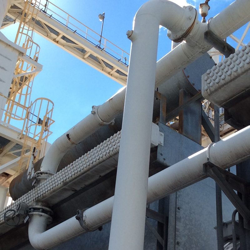
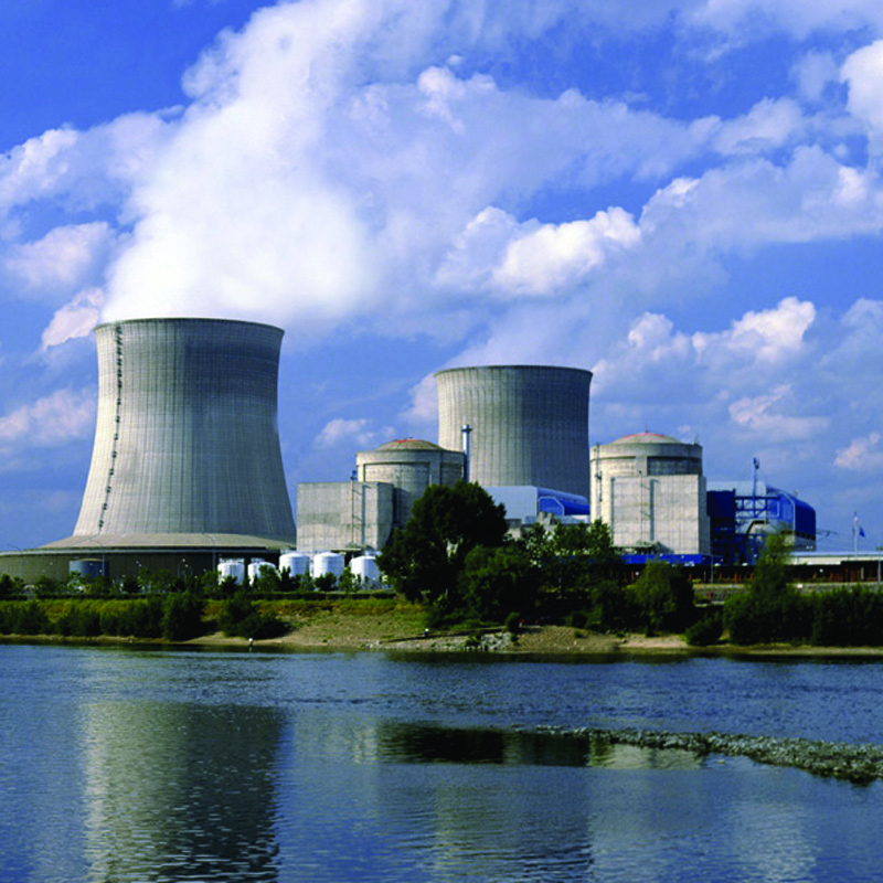
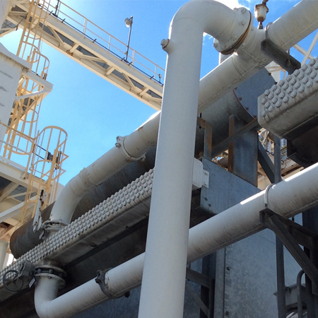
In a generating station, any forced outage is costly, especially at the peak of the generating season. All plants that support the base load of energy need to do everything possible to maximize uptime.

As an example of the costs associated with unplanned outages, a Coal-fired Generation plant incurred almost $10.9 million in losses due to almost 1369 hours (over 8 weeks) of downtime due to process water contamination. Causes for the failures were varied but one of the single largest (34%) was due to the failure of previously installed rubber condenser plugs!

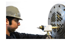
These outages call for a proactive change out of old rubber/elastomer tube plugs to the Pop-A-Plug Tube Plugs for reliable, permanent sealing of leaking and degraded tube plugs.

Pop-A-Plug Tube Plugs are proven to provide the lowest lifecycle cost for all types of plug systems used in heat exchanger maintenance.

Pop-A-Plug Tube Plug kits are available with 24/7 emergency service for any unplanned outage that may arise – anywhere. EST Group also offers outage job boxes for large plants needing a variety of plugs for their condenser systems.

The Engineered Solution

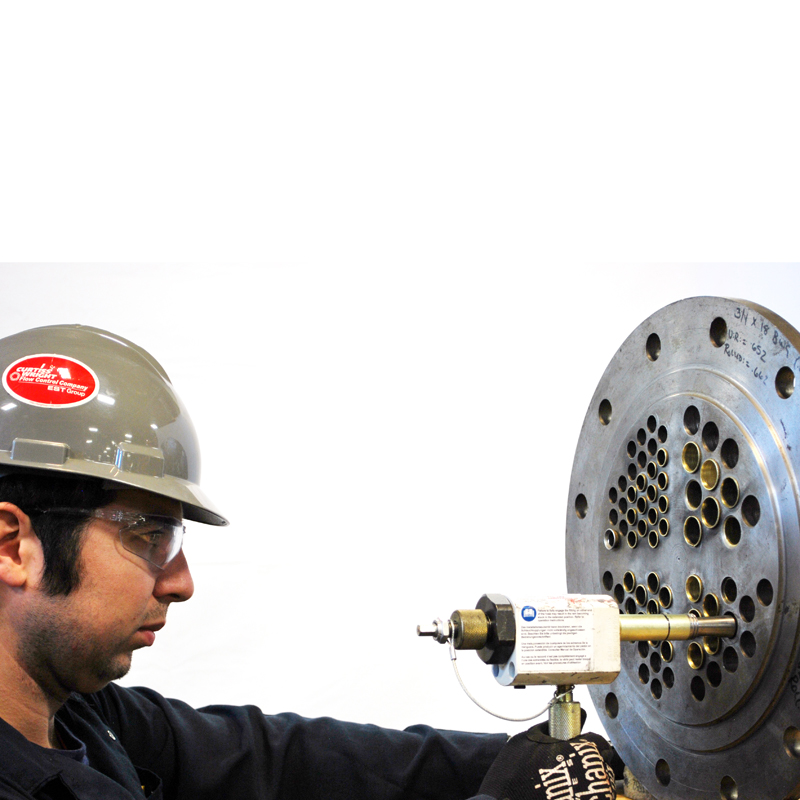
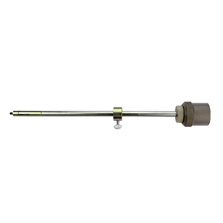
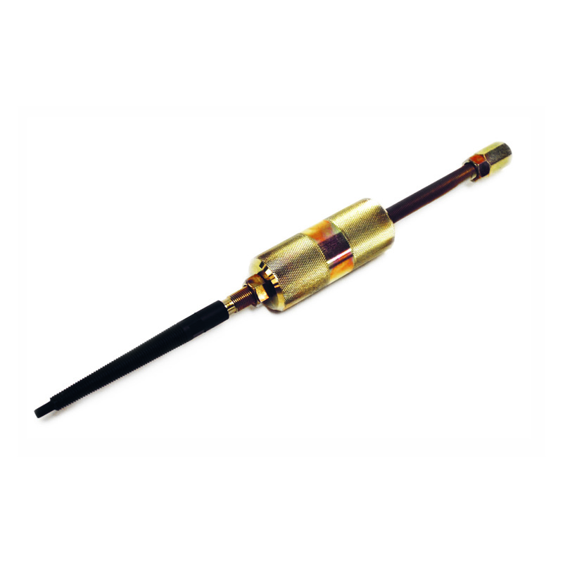
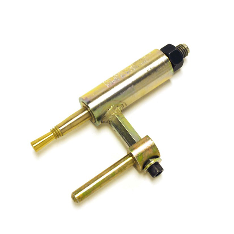
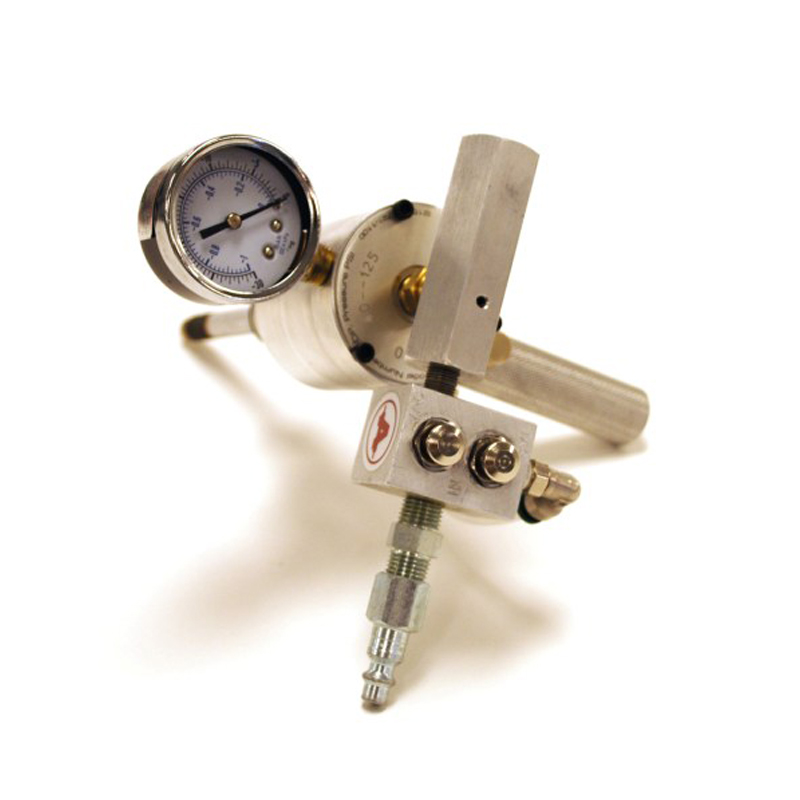
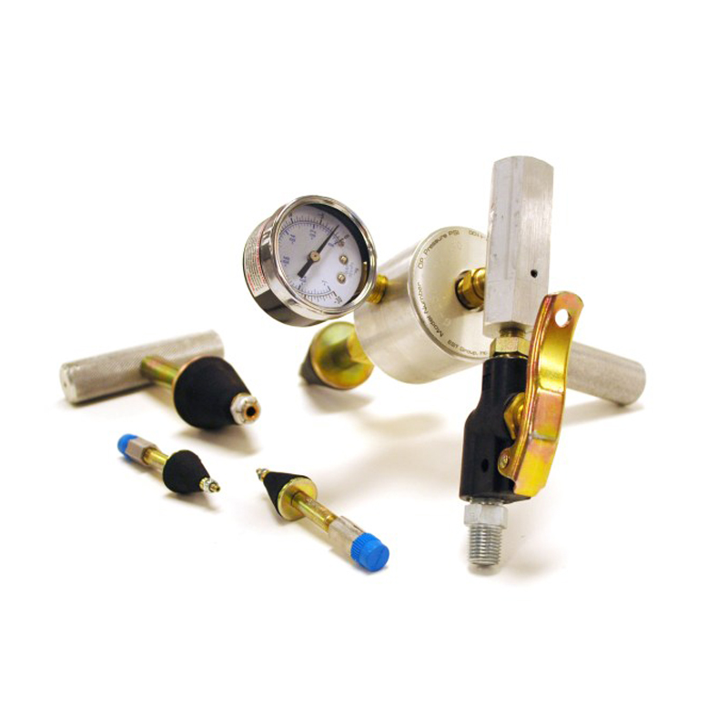
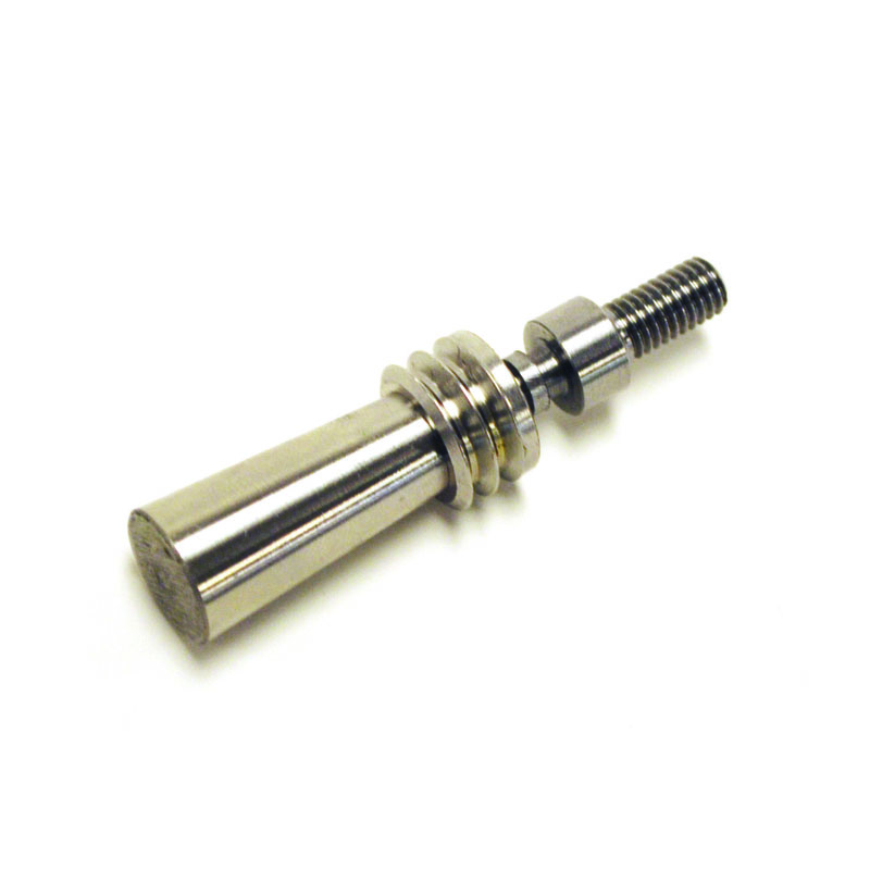
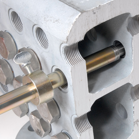
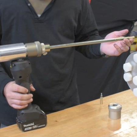
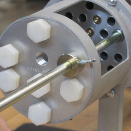
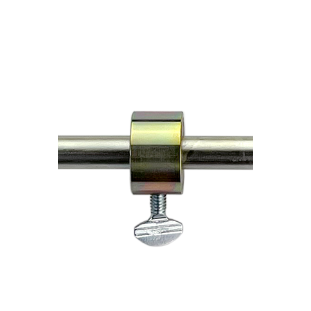
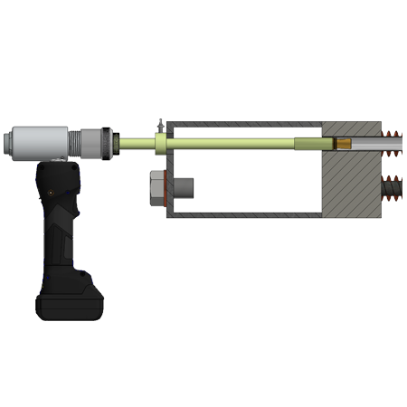
Pop-A-Plug Tube Plugs have a unique internally serrated pin/ring seal design constructed of the same material as the tube metal, providing a reliable helium leak-tight seal. Installation is always a precisely controlled and repeatable process. Pop-A-Plug Tube Plugs are acceptable for use in coated tubes and tubesheets as well with no damage to the tubes or tubesheets.

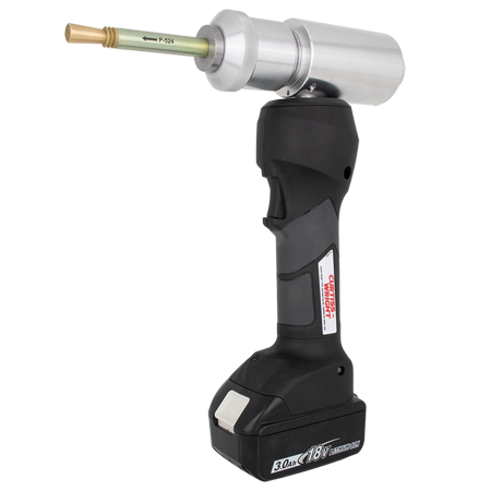
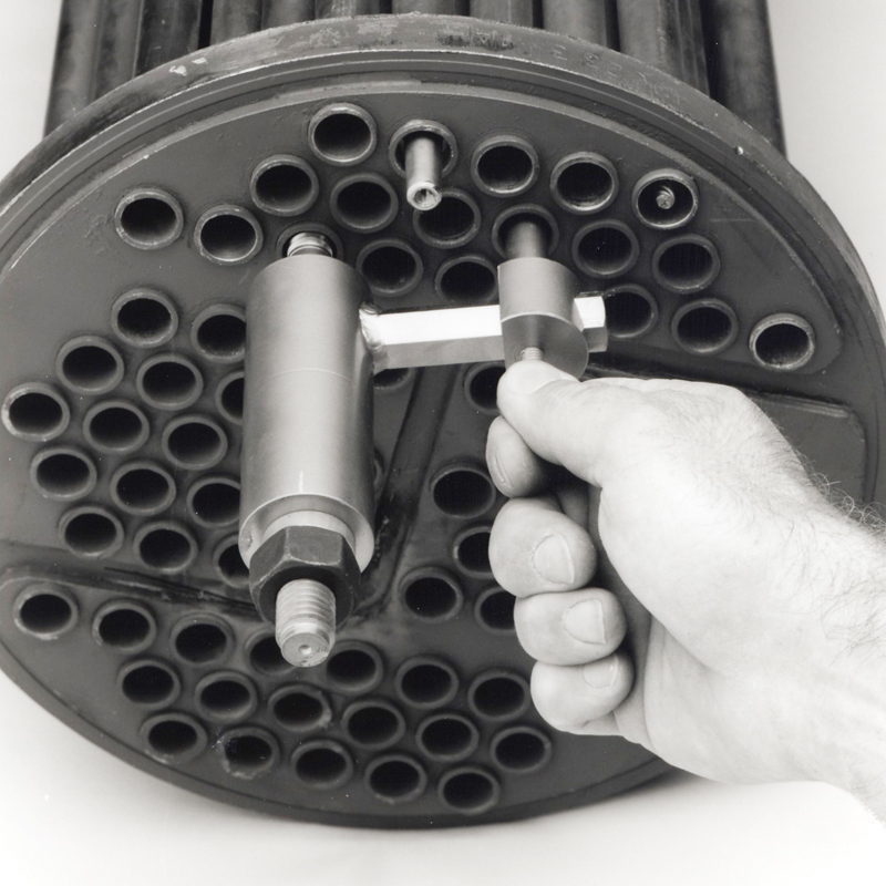
Pop-A-Plug CPI/Perma plugs are rated at 1000 PsiG (69 BarG) for safe consistent plugging. And since the plug material is always matched to the tube material, thermal expansion is always consistent between the tube and the plug, eliminating the opportunity for thermally induced leaks. In addition, the installation tooling is designed for easy use to reduce fatigue and minimize the need to enter confined spaces to do the repair work, and no welding of any kind is ever required!

Top 5 Reasons to Replace Elastomer/Polymer Plugs with
Pop-A-Plug® Tube Plugs

      1. You have leaking condenser plugs resulting in cooling water inleakage, causing increased forced outage hours
      2. You have experienced increased water chemistry costs attributed to inleakage
      3. You have had secondary equipment failures caused by inleakage
      4. You have incurred increased costs to identify leaking or compromised tube plugs
      5. You have had Loss of Offsite Power (LOOP) events (Nuclear Power Plants) and the elastomer plugs you are using are degrading and expelling

Curtiss Wright EST is committed to minimizing plant downtime with our condenser plugs. Any forced outage is costly, so we provide an engineered solution that is suitable for your application.

Choose the Industry Standard!!

Pop-A-Plug Tube Plugs have been the industry standard, in use by 95% of all Nuclear Power plants in the USA.

Recognized by:

  • NUPIC 10CFR50 ApB; NOA-1
  • TUV
  • EPRI
  • ASME PCC-2
  • US Navy
  • CRN


For more information or to receive information on how Pop-A-Plug Tube Plugs provide the best return on your repair investment contact us.
We’ll send you the facts you need to know!

Product Images

CAPTCHA
This question is for testing whether or not you are a human visitor and to prevent automated spam submissions.

DFR Rotary Spring & Diaphragm Actuator

Submitted by divya on July 9, 2025
Rotary Spring & Diaphragm

DFR Rotary Spring & Diaphragm Actuator

  • 0-18 PSIG (0-1.24 BARG) or 0-33 PSIG (0-2.28 BARG) Input Signal
  • 1/2" (12.7mm) to 2" (50.8mm) Valve Shaft Compatibility
  • -40°F to 180°F (-40°C to 82°C) Standard Temperature Limitations

More Details

Model DFR rotary spring and diaphragm actuators are large diaphragm area actuators that allow for low-pressure operation. The spring provides fail safe positioning for a control valve on loss of pneumatic supply pressure. DFR actuators can be used to automate control valves for throttling or on/off control of liquids or gases.

Overview

Options
 
  • Handwheels and Travel Stop Options Available
  • Versatile Instrument Mounting Options
  • Field Reversable
  • Heavy Duty Protective Coatings Available

Print

|

Back to Top

Product Specifications

DFR Specifications
 
AVAILABLE DFR DIAPHRAGM CASING VOLUMES
CASING SIZE CLEARANCE VOLUME (1) CASING VOLUME (2)
60 DEGREE ROTATION 90 DEGREE ROTATION
INCH3 cm3 INCH3 cm3 INCH3 cm3
26 40 655 67 1,098 76 1,245
47 38 623 115 1,890 146 2,390
70 64 1,050 250 4,100 330 5,410
156 216 3,540 708 11,600 927 15,200
220 213 3,490 850 13,929 1,161 19,025
NOTES: Volume when the diaphragm is in the up position.
This value includes the clearance volume.
AVAILABLE VAVLE SHAFT COMPATIBILITY
ACTUATOR SIZE VALVE SHAFT SIZES
1/2" (12.7mm) 5/8" (15.9mm) 3/4" (19.1mm) 7/8" (22.2mm) 1" (25.4mm) 1-1/4" (31.8mm) 1-1/2" (38.1mm) 1-3/4" (44.5mm) 2" (50.8mm)
026 ü û û û û û û û û
047 ü ü ü û û û û û û
070 ü ü ü ü ü û û û û
156 û û ü ü ü ü ü û û
220 û û û û û ü ü ü ü
AVAILABLE OUTPUT TORQUE WITH 23 PSIG (1.59 BAR) SUPPLY PRESSURE - 0-18 PSIG (0-1.24 BAR) OPERATING RANGE
ACTUATOR SIZE ACTUATOR SPRING CODE ACTION
FAIL OPEN FAIL CLOSED
TORQUE START STROKE TORQUE START STROKE
BREAKOUT OPERATING BREAKOUT  OPERATING
lbf-in N•m lbf-in N•m PSIG BARG lbf-in N•m lbf-in N•m PSIG BARG
026 A 130 15 130 15 3 21 90 10 200 23 3.9 27
047 C 172 19 399 45 3 21 336 38 170 19 4.9 34
070 D 380 43 980 111 3 21 730 82 620 70 4.3 30
156 K 2,140 242 2,320 262 3 21 1,630 184 3,160 357 3.7 26
070 I 770 87 890 101 3 21 520 59 1,290 146 3 21


AVAILABLE OUTPUT TORQUE WITH 38 PSIG (2.62 BAR) SUPPLY PRESSURE - 0-33 PSIG (0-2.28 BAR) OPERATING RANGE
ACTUATOR SIZE ACTUATOR SPRING CODE ACTION
FAIL OPEN FAIL CLOSED
TORQUE START STROKE TORQUE START STROKE
BREAKOUT OPERATING BREAKOUT  OPERATING
lbf-in N•m lbf-in N•m PSIG BARG lbf-in N•m lbf-in N•m PSIG BARG
026 B 280 32 160 18 3 21 160 18 370 42 6.8 47
047 C 807 91 555 63 4.9 34 334 38 1,139 129 4.9 34
047 H 977 110 521 59 3 21 440 50 1,162 131 6.3 43
070 D 1,960 221 1,260 142 4.3 30 730 82 3,050 344 4.3 30
070 E 1,409 156 1,174 133 3 21 1,030 116 1,820 206 6 41
156 F 4,160 470 3,020 341 3 21 3,090 349 4,760 538 7 48
070 G 5,720 646 3,690 417 3 21 4,810 543 5,540 626 10.1 70


AVAILABLE OUTPUT TORQUE WITH 32 PSIG (2.21 BAR) SUPPLY PRESSURE - 3-27 PSIG (21-1.86 BAR) OPERATING RANGE
ACTUATOR SIZE ACTUATOR SPRING CODE ACTION
FAIL OPEN FAIL CLOSED
TORQUE START STROKE TORQUE START STROKE
BREAKOUT OPERATING BREAKOUT  OPERATING
lbf-in N•m lbf-in N•m PSIG BARG lbf-in N•m lbf-in N•m PSIG BARG
026 A 164 222 67 91 3.9 27 N/A N/A N/A N/A N/A N/A
026 B 163 221 73 99 3.1 21 89 121 218 296 6.8 47
047 C 591 801 270 366 4 28 147 199 787 1,067 4.9 34
047 H 364 494 270 366 3.1 21 249 338 375 508 6.3 43
070 D 1,432 1,942 543 736 3.4 23 218 296 2,082 2,823 4.3 30
070 E 662 898 644 873 3.1 21 517 701 845 1,146 6 41
070 I 1,010 1,369 364 494 3.1 21 N/A N/A N/A N/A N/A N/A
156 F 2,156 2,919 1,649 2,236 3.1 21 1,776 2,408 2,135 2,895 7 48
156 K 2,970 4,027 1,338 1,814 3.7 26 N/A N/A N/A N/A N/A N/A
070 G 2,989 4,053 1,880 2,549 3.1 21 N/A N/A N/A N/A N/A N/A

Printable view

DFR Actuator Documentation

Refer to our FloSpec software for product selection, sizing and ordering

supplier

Pop-A-Plug® Tube Plugging System for Air-Cooled Heat Exchangers

Submitted by Shilpa on July 9, 2025

Pop-A-Plug® Tube Plugging System for Air-Cooled Heat Exchangers


Pop-A-Plug® Tube Plugging System for Air-Cooled Heat Exchangers

Tube leaks in ACHE units (Fin Fan coolers) can be difficult to identify and repair due to the limited access to the tubesheet through the plugsheet. Typically when leaks in the tubes are identified they are plugged by using tapered hammer-in plugs, or in higher pressure ACHE units, the plugs have to be welded in place.

In both cases, the damage frequently occurs to the tubesheet, plugsheet, and/or adjacent tubes. Pop-A-Plug Air Cooled Heat Exchanger Tube Plugging System offers significant advantages over hammer-in or welded plug applications for the following reasons:

  • Average installation time: ~2 mins./plug
  • No weld permits required
  • No expert welders required
  • Consistent and repeatable installation
  • Accommodates Through-the-Tube Plugging applicationsNo damage to plugsheet threads, tubesheet or adjacent tubes.
  • Permanent sealing solution with removability option

Related products


To see how the Pop-A-Plug Tube Plugging System bypasses the void space and plugs leaking tubes, watch the video below:


Features & Benefits

  • Unmatched Performance Under Pressure: Pop-A-Plug® CPI/Perma plugs are conservatively rated for 1,000 psi (68.9 Bar) service.
  • Reliable and Leak Tight: Properly installed, Pop-A-Plug® CPI/Perma plugs stay installed and are helium leak tight to 1x10 -10 cc/sec.
  • Quick Installation Minimizes Downtime: Pop-A-Plug® CPI/Perma plugs are simple mechanical plugs which can be installed hydraulically in minutes without damaging the tube, tubejoint or tubesheet. Installs using standard Pop-A-Plug System Ram Package or Manual Installation Tool.
  • Easy Sizing and Installation: Use PAP Tube Cleaning Brush to prepare the tube end, gauge the tube with a PAP Go / No-Go Gage, select the matching plug size and POP. Pop-A-Plug® CPI/Perma plugs may be removed using the Pop-A-Plug Removal Tool when its time to retube.
  • Broader Expansion Range: Depending on the plug size, individual Pop-A-Plug® CPI/Perma plugs can expand up to .13" (3.3 mm), reducing the number of plugs sizes required on hand.
  • Materials: Always match Pop-A-Plug® CPI/Perma plugs to the tube material. Pop-A-Plug® CPI/Perma plugs are available for immediate shipment in stainless steel 316, carbon steel and brass. Titanium and other alloys can be supplied by request - Contact factory.
  • Ordering Information: When ordering, specify tube OD and wall thickness or measured tube ID, tube material, tubesheet material if plug will be installed directly into tubesheet, maximum pressure and temperature, type of tube to tubesheet joint (rolled, welded, etc.) and condition of tubes and age of heat exchanger. Specifications subject to change.
  • Quality Assurance System: Manufactured under a Quality Assurance Program certified to ISO 9001 and several U.S. nuclear power industry standards including ANSI N45.2, NQA-1, 10CFR 50 Appendix B, and 10CFR 21.
Product Images

CAPTCHA
This question is for testing whether or not you are a human visitor and to prevent automated spam submissions.

DFC & DFO Linear Spring & Diaphragm Actuators

Submitted by divya on July 8, 2025
Linear Spring & Diaphragm

DFC & DFO Linear Spring & Diaphragm Actuators

  • 3-15 PSIG (0.21-1.03 BARG) or 6-30 PSIG (0.41-2.07 BARG) Input Signal
  • 3/8" (9.5mm) | 1/2" (12.7mm) | 3/4" (19.1mm) Valve Stem Compatibility
  • 2-1/8" (54mm) | 2-13/16" (71mm) |  3-9/16" (90mm) Yoke Boss Size
  • -40°F to 180°F (-40°C to 82°C) Standard Temperature Limitations

More Details

Model DFC (Fail Closed) and DFO (Fail Open) linear spring and diaphragm actuators are large diaphragm area actuators that allow for low-pressure operation. The spring provides fail safe positioning for a control valve on loss of pneumatic supply pressure. Both DFC and DFO actuators can be used to automate control valves for throttling or on/off control of liquids or gases.

Overview

Options
 
  • Open Yoke / Open Valve Stem Design
  • Heavy Duty Protective Coatings Available
  • Handwheels and Travel Stop Options Available
  • Versatile Instrument Mounting Options

Print

|

Back to Top

Product Specifications

DFC / DFO Specifications
 
DFC ACTUATOR SPECIFICATIONS
SPECIFICATIONS ACTUATOR SIZE
1046 1069 2069 2105 2156 3105 3156 3220 (1)
NOMINAL EFFECTIVE AREA INCH2 46 69 69 105 156 105 156 220
cm2 297 445 445 667 1,006 677 1,006 1,419
YOKE BOSS SIZE INCH 2-1/8 2-1/8 2-13/16 2-13/16 2-13/16 3-9/16 3-9/16 3-9/16
cm 54 54 71.5 71.5 71.5 90.5 90.5 90.5
ACCEPTABLE VALVE STEM DIAMETER INCH 3/8 3/8 1/2 1/2 1/2 3/4 3/4 3/4
mm 9.5 9.5 12.7 12.7 12.7 19.1 19.1 19.1
MAXIMUM ALLOWABLE OUTPUT THRUST lb 2,300 2,300 2,700 5,650 7,550 5,650 6,800 8,800
N 10,230 10,230 12,010 25,132 33,584 25,132 30,248 39,144
MAXIMUM TRAVEL (2) STANDARD INCH 3/4 1-1/8 1-1/2 2 2 2 2 (3)
mm 19.1 28.6 38.1 50.8 50.8 50.8 50.8 76.2
TOP-LOADED INCH N/A 3/4 N/A 3/4 N/A N/A 1-1/8 N/A
mm N/A 19.1 N/A 19.1 N/A N/A 28.6 N/A
MAXIMUM CASING PRESSURE FOR ACTUATOR SIZING (4,5) PSIG 55 70 70 65 55 65 55 50
BARG 380 483 483 448 379 448 379 345
MAXIMUM EXCESS DIAPHRAGM PRESSURE (4) PSIG 55 20 20 10 10 10 10 10
BARG 380 138 138 69 69 69 69 69
MAXIMUM DIAPHRAGM CASING PRESSURE (4,5) PSIG 110 90 90 75 65 75 65 60
BARG 760 621 621 517 448 517 448 414
MATERIAL TEMPERATURE CAPABILITIES NITRILE -40°F to 180°F (-40°C to 82°C)
SILICONE -40°F to 180°F (-40°C to 82°C)
NOTES: (1) These values also apply to the DFC Size 3220-4 actuator.
(2) Actuator travel may be less than the value listed after connected to the valve.
(3) Maximum actuator travel for the 3220-4 is 4 inches (102 mm).
(4) Additional pressure may be added to the actuator when the actuator is at full travel. Damage to the actuator will occur if the Maximum Excess Diaphragm Pressure is exceeded. When the actuator has reached its full travel, and the diaphragm plate is physically stopped from moving, the energy from additional pressure is transferred to the diaphragm and casing. The amount of excess pressure that can be added at full travel is limited, exceeding this limiting factor will result in damage to the actuator, leakage, and/or casing fatigue or deformation.
(5) This Maximum Casing Pressure is not to be used for normal operating pressure. Its purpose is to allow for typical regulator supply settings and/or relief valve tolerances. The maximum casing pressure is the pressure that can be applied to the actuator when the actuator is at less than full travel. Damage to the actuator may occur if this pressure is exceeded before the full travel is reached.
DFO ACTUATOR SPECIFICATIONS
SPECIFICATIONS ACTUATOR SIZE
1046 1069 2069 2105 2156 3105 3156 3220 (1)
NOMINAL EFFECTIVE AREA INCH2 46 69 69 105 156 105 156 220
cm2 297 445 445 667 1,006 677 1,006 1,419
YOKE BOSS SIZE INCH 2-1/8 2-1/8 2-13/16 2-13/16 2-13/16 3-9/16 3-9/16 3-9/16
cm 54 54 71.5 71.5 71.5 90.5 90.5 90.5
ACCEPTABLE VALVE STEM DIAMETER INCH 3/8 3/8 1/2 1/2 1/2 3/4 3/4 3/4
mm 9.5 9.5 12.7 12.7 12.7 19.1 19.1 19.1
MAXIMUM ALLOWABLE OUTPUT THRUST lbf 2,300 2,300 2,700 5,650 7,550 5,650 6,800 8,800
N 10,230 10,230 12,010 25,132 33,584 25,132 30,248 39,144
MAXIMUM TRAVEL (2) INCH 3/4 1-1/8 1-1/2 2 2 2 2 (3)
mm 19.1 28.6 38.1 50.8 50.8 50.8 50.8 76.2
MAXIMUM CASING PRESSURE FOR ACTUATOR SIZING (4) PSIG 125 65 65 50 40 50 40 55
BARG 862 448 448 345 276 345 276 379
MAXIMUM DIAPHRAGM CASING PRESSURE (4,5) PSIG 140 75 75 60 50 60 50 65
BARG 965 517 517 414 345 414 345 448
MATERIAL TEMPERATURE CAPABILITIES NITRILE -40°F to 180°F (-40°C to 82°C)
NOTES: (1) These values also apply to the DFO Size 3220-4 actuator.
(2) Actuator travel may be less than the value listed after connected to the valve.
(3) Maximum actuator travel for the 3220-4 is 4 inches (102 mm).
(4) The Operating Diaphragm Pressure must not exceed the Maximum Diaphragm Casing Pressure and must not produce a force on the actuator stem greater than the maximum allowable valve stem load.
(5) This Maximum Casing Pressure is not to be used for normal operating pressure. Its purpose is to allow for typical regulator supply settings and/or relief valve tolerances. The maximum casing pressure is the pressure that can be applied to the actuator when the actuator is at less than full travel. Damage to the actuator may occur if this pressure is exceeded before the full travel is reached.

Printable view

DFC & DFO Actuator Documentation

Refer to our FloSpec software for product selection, sizing and ordering

supplier

Air Cooled HX Installation Tools

Submitted by Shilpa on July 8, 2025

Air Cooled HX Installation Tools


Smart Ram 640T ACHE Adapter

Install Pop-A-Plug Tube plugs in Air Cooled Heat Exchangers with our Smart Ram 640T Cordless installation tool.

Size Range Capability

  • Pop-A-Plug® CPI/Perma Plugs: V471 to V1212
    - Tube ID: 0.472” to 1.336” (11.99 mm - 33.93 mm)
  • Pop-A-Plug® P2 Plugs: P2400 to P21160
    - Tube ID: 0.400” to 1.180” (10.19 mm - 29.99 mm)


Features

  • Working pressures to 7000 PsiG (480 BarG)
  • Helium leak tight to 1x10⁻¹⁰ cc/sec
  • 12” (30 cm) extension length


Benefits

  • Safe − installed plugs will not leak or eject under pressure
  • Convenient − no hot work permits, or welding required
  • Fast − return units to service as fast as 1/10th the time of welding
  • Portable − ideal for remote work locations, no electric/air supply needed
  • Provides ASME PCC-2 compliant tube repair
  • Eliminates tripping hazards
  • No damage to header box plug threads, tubes, tube joints or tubesheets
  • Stand-Off ring allows for precise and uniform plug installation
  • No foreign material (break-away) left after installation
  • Lowest installed cost compared to conventional plugging methods


Related Videos


Contact Sales to place an order or request a quote.

Product Images

CAPTCHA
This question is for testing whether or not you are a human visitor and to prevent automated spam submissions.

Pop-A-Plug® Removal Tool

Submitted by Shilpa on July 8, 2025

Pop-A-Plug® Removal Tool


For Fast, Reliable Removals - No Air or Electricity Needed

  • Removes Installed Plugs Quickly and Easily
  • Works on All Styles of Pop-A-Plugs®


EST's Pop-A-Plug® Removal Tool (PRT) is the ideal companion to our Pop-A-Plug Installation Tools - perfect for removing installed Pop-A-Plugs when it comes time to retube, sleeve or retire the bundle.

EST’s Plug Removal Tool combines a tube spear and slide hammer. Simply thread the spear tip into the exposed Pop-A-Plug pin, use the slide hammer to drive the pin back through the ring separating the plug components, tighten the spear into the ring 4-6 revolutions, and use the slide hammer to pull the ring and pin from the tube end.

The three-piece PRT consists of a main body shaft, a spear, and a slide hammer. Different spears are available to remove any size and P2 or Pop-A-Plug® CPI/Perma Heat Exchanger Tube Plug.

Product Images

CAPTCHA
This question is for testing whether or not you are a human visitor and to prevent automated spam submissions.

Pop-A-Plug® Manual Installation Tool

Submitted by Shilpa on July 7, 2025

Pop-A-Plug® Manual Installation Tool


Fast, Reliable Tube Plug Installation when No Air or Electricity Needed

  • Manually Install plugs quickly and easily
  • Compatible with all types of Pop-A-Plug Tube Plugs


The Pop-A-Plug Manual Installation Tool (MIT) is the perfect companion to our Hydraulic Ram Packages, providing fast, reliable installation when no air or electricity are available.

Tool comes complete with Pull Rod and Positioner to install the size and style Pop-A-Plug identified in the tool's model number. The MIT body will accept all pull rods and positioners for P2 tube plugs up to 1.160" and Pop-A-Plug Air-Cooled Heat Exchanger tube plugs up to 1.149".

The MIT can be used with manual wrenches or sockets, as well as with electric or pneumatic impact wrenches.

Product Images

CAPTCHA
This question is for testing whether or not you are a human visitor and to prevent automated spam submissions.

G-650 Vacuum Joint Testing Tool

Submitted by Shilpa on July 7, 2025

G-650 Vacuum Joint Testing Tool


Quickly seal off and evacuate individual heat exchanger tubes to test the tube for leakage​

G-650 Vacuum Joint Testing Tool quickly test expanded tube-to-tubesheet joints for leakage. Ideal for heat exchanger manufacturers or companies performing retubing operations. The G-650 Tool seals the tube ID and along the tubesheet face, then evacuates the tube end at the joint. A loss of vacuum indicates a leaky tube joint.

The G-650 Vacuum Joint Testing Tool operates on standard plant air supplies from 40 to 125 psi (2.7-8.6 bar). A highly efficient venturi creates 21-24 in-Hg (707 to 808 mBar) vacuum on an inlet air supply of 100 psi (6.8Bar) and 10 SCFM. Interchangeable Manifolds, and Seal and Washer Sets allow the G-650 to test tube-to-tubesheet joints on 3/8" OD to 1-1/4" (9.53mm to 31.75mm) OD tubes sizes from 0.280" to 1.230" (7.11mm to 31.24mm) I.D. The larger G-650A Joint Testing Tool will accommodate 1-1/2" to as large as 2-1/2" tube sizes.

G-650 Vacuum Joint Testing Tools are not suitable for testing excessively belled / flared tube ends, or tubes with welded tube-to-tubesheet joints.

Specify the following information when ordering:

  • Tube OD and wall thickness
  • Number of tubes to be tested
  • Tube pitch and spacing (if known)
  • Length or depth of any channel head present


Features & Benefits

  • Manufacturers or Retubing: Ideal for heat exchanger manufacturers or companies performing retubing operations.
  • Easy to detect leaks: Seals the tube ID and along the tubesheet face, then evacuates the tube end at the joint. A loss of vacuum indicates a leaky tube joint.
  • Uses standard air supplies: Operates on standard plant air supplies from 40 to 125 psi (2.8-8.6 bar). A highly efficient venturi creates 21-24 in-Hg (707 to 808 mBar) vacuum on an inlet air supply of 100 psi (6.8Bar) and 10 SCFM.
  • Interchangeable Manifolds, Seal and Washer Sets: This allow the G-650 to test tube-to-tubesheet joints on 3/8" OD to 1-1/4" (9.53mm to 31.75mm) OD tubes sizes from 0.280" to 1.230" (7.11mm to 31.24mm) I.D. The larger G-650A Joint Testing tool will accommodate 1-1/2" to as large as 2-1/2" tube sizes.
Product Images

CAPTCHA
This question is for testing whether or not you are a human visitor and to prevent automated spam submissions.

G-250 Vacuum Tube Testing Tool

Submitted by Shilpa on July 7, 2025

G-250 Vacuum Tube Testing Tool


Provides a fast and effective way to seal off and evacuate individual heat exchanger tubes to test the tube for leakage.

  • Pneumatically Test Heat Exchanger Tubes
  • Test Tube-to-Tubesheet Joints for Leaks


G-250 Vacuum Tube Testing Tools are designed to quickly seal off and evacuate individual heat exchanger and vacuum tubes to test the tube for leakage.

Requirements

  • Plant air supply between 40 and 125 psi (2.7 to 8.6Bar)
  • Air supply flow rate greater than 5 SCFM (2.36lps

Features & Benefits

  • Supplied with two sizes of interchangeable conical neoprene Seal and Washer Sets and a compact toolbox
  • Test heat exchanger tubes ranging from 0.28" to 1.45" (7.1mm to 36.8mm) ID
  • Durable - machined from high strength aluminum alloy
  • Light Weight - each set weighs less than 2.5 lbs (1.1kg), reducing fatigue associated with heavier testing equipment
 

Additional Information

Specify the following information when ordering:

  • Tube OD and wall thickness
  • Tube length, tubesheet face-to-face dimension
  • Number of tubes to be tested
  • Length or depth of any channel head or header box present

Operating the G-250 Vacuum Tube Testing Tool

      1. Connect the standard plant air supply to the active vacuum gun and insert the conical seal into the end of the tube to be tested.
      2. Insert the passive plugging tool into the opposite end of the tube.
      3. Depress the air control valve, air flows through the vacuum generator and evacuates the tube.
      4. Release the air control valve and any loss of vacuum indicated on the vacuum gauge identifies a leaking tube.


An optional digital vacuum gauge increases the operator’s ability to detect even the smallest pinhole leaks.

Product Images

CAPTCHA
This question is for testing whether or not you are a human visitor and to prevent automated spam submissions.
Subscribe to
print