1890 Series - Process Valve
Farris
- Threaded Steel PRV
- ASME/NB Certified – Air, Steam & Water
- Full Bore Nozzle Design

Farris
|
Back to Top
Printable view
Please log in or register to use our model configurator, with this you can view and download 3D and 2D models and drawings, as well as build and submit a quote request.
Models and drawings are for illustrative purposes only and may change. Please contact your local representative for additional details.
Farris
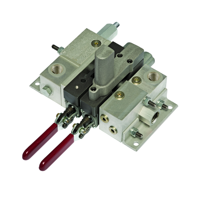
Directional control valves allow fluids or gases to flow into different paths from valve ports, which provide a passageway for flow to or from other components/sources. They are one of the most important parts of hydraulic and pneumatic systems.
A directional control valve consists of a mechanically or electrically actuated spool inside a cylinder. The spool’s position allows or prevents fluid flow within the passageway; this often occurs instantly, causing fluid to accelerate and decelerate rapidly.
|
Back to Top
Hydraulically operated directional control valves are much more robust than other operation methods. In addition, they are designed to be more precise as they perform at much higher pressures than a pneumatic directional control valve.
Manual operated valves are operated with levers or paddles that require force to open and close the valve. Occasionally spring force is required to recover the valve position. In contrast, some manual valves use a lever or external pneumatic or hydraulic signal to return the spool to its original position.
Mechanically operated valves are more subject to wear and tear as they apply force by using cams, wheels, and rollers.
Printable view


 SizeMaster - Relief System Sizing Software
 Directional Control Valves
 4700 Series - Steam Safety Valve
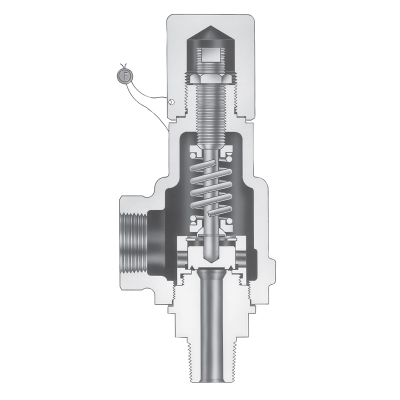 1896 Series - Steam Safety Valve
 6400 Series - Steam Safety Valve
 4200 Series - Steam Safety Valve
 2700 Series - Process Valve - Pressure Relief Valve
 3800 Series - Process Valve